Mike Strong - CV Illustration

Software product and product sheet

NOTE: This page is a compilation of several pages as part of the product description in the 1990's.

I wrote the software and all the interfaces. I also did the screen captures you see below and the text and arrangement of the web pages.

Note: AutoScript is no longer available. Development and production were shut down in September 1998. For several years after you could still use a competing program for these and other functions, CAD Publisher. That now appears to be defunct. See the box at the bottom of this page.


AutoScript® Product Sheet


AutoScript is a fancy file convertor which takes an AutoCad drawing file and produces a PostScript or an Encapsulated PostScript file from it. That output file is then suitable for use as an illustration either directly as a presentation piece or for pre-press use. It is used greatly in the screen printing industry, especially for control panels, printed circuit boards and membrane key pads.

 
AutoScript offers three very major advantages over AutoCad output - or any other file conversion program :

  1. A quick and consistent method of setting colors, fills, and line specs for a range of entities based on their color in AutoCad.
  2. Control over linewidths, fills over any closed entity, creation of any color and halftone-cell control for pre-press.
  3. The original AutoCad drawing is not messed with or changed. Output settings are saved in an AutoScript "config" file.
 

The table below controls how the drawing will process
from within AutoScript.

The color for any cell will be shown by name in the pull-down list box on the top left and by display example in one or both of the color-swatch boxes (labeled "Stroke" and "Fill") just to the right of the pull-down. The button in the upper left (here showing as "On") toggles any row on or off (output or no output) and always shows the on/off status of the current row, as does the "on" or "off" in the far left side of the far left column. 
  
Note that entities by category (text, circle, pline, etc) are the column titles to the right of "default color" and that there is a fill and a stroke column for each. This allows you to fill with one color and stroke with another color.

 
Processing Order - In this example (using entity colors - note: by layer is also available), the output is handled so that entities drawn in the color red are processed first, then those drawn in blue (color #7) are second and so forth. The order in which the colors are drawn can be easily changed by clicking the "Process Order" button (lower left of table). This brings up a small dialog with a list box in which you can drag the rows into a different order. 
 
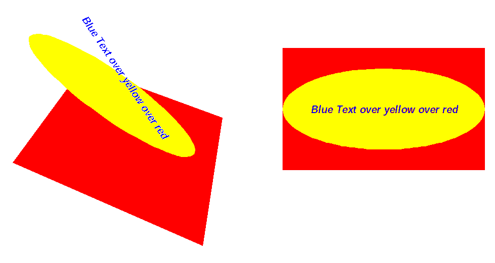
Essentially you should think of each row in the same manner you think of printing one color after (on top of) another when screen printing. When preparing an AutoCad drawing for use in this manner you should think of the AutoCad color numbers as representing back-to-front images for processing. 
 

In this example in the exploded view on the left the rectangle is drawn in red, the ellipse in yellow and the text in blue. In AutoScript we set up a processing order in which red entities processed first, then yellow entities and finally blue entities. This produces the result to the right. 
  
Please note: For this example, we used the same colors for output as the colors in which the entities are drawn. For example entities in red we filled with red. However, entities can be assigned totally different output colors by AutoScript. We could just as easily have created a gradient purple to azure color and filled the same red entities with that color.

We used the term "process rows" for what other programs might call a "layer," to represent bottom-to-top (or back-to-front) order of processing for portions of a full image (i.e. PhotoShop, Illustrator). The reason we did not use "layer" as our term was to avoid confusion with AutoCad's use of the term "layer." In AutoCad layers are not used to control order of processing. In AutoCad layers are arbitrary (usually descriptive names) used to group object categories within images. For example a drawing of a house might have the layer "PLUMBING" used to show plumbing pipes, sinks, toilets, etc. The layer "ELECTRIC" might show wiring, junction boxes. etc. 
  
File - This column controls which rows will be put together to produce output files Files are designated as "A" or "B" or "C" and so forth to "Z" at max.  
Each set of rows designated as a file produces a printing plate. You also have an option in the print dialog to send out each row as a separate file. 
  
Line width - Lines for entities in this row will be drawn to the width specified in the line width column. This setting defaults to an absolute width (that is the width is set for output on paper) or a world (scaled) width so that the size of the output proportionaly affects the width of the line. When polylines are given a width in the drawing that is the width assigned to that particular polyline. This includes polylines with varying widths. 
  
Default Color - This is the color used for the entity-color assignments unless changed by the user. To change a color assignment you simply click on the pull-down list box in the upper left and select one of the currently available colors. You can also highlight a range of cells and change the colors for that entire range of cells. 
  
EntityName Stroke (Outline) - This allows you to set a line-draw color for the named entity separately from any fill color. In the case in which you might choose a gradient color the first color in the gradient is used for the line color. 
  
EntityName Fill (Solid) - This allows you to set a color with which to fill an entity (separately from any line-draw color). These can be any of the colors defined as part of the drawing configuration file. In the case of PSFills or Solid Color Fills set in AutoCad these will be recognized as the drawing processes and will be substituted for any setting here. The reasoning is that if you specified, in AutoCad, a certain fill color then that color definition should take precedence (just like the polyline linewidth setting). 
  
Line Control button - This brings up a separate dialog which floats over the table view which allows you to make row-by-row exceptions to the overall (global) line-control settings. 
  
Edit Colors button - This allows you to edit and / or create color definitions. 
 

See These AutoScript Dialogs


Setting Color Definitions 

AutoScript does not limit you to the 255 defined colors in AutoCad. You are able to create any number of colors simply by assigning proportions to each colorant for each color definition.


There are three main tabbed areas: 
1 - The library is any of a set of FoxBase databases which provide sets of defined colors you can add to any current drawing. 
2 - The Config is the set of colors specifically assigned to this particular drawing. 
3 - Transfers is the panel which allows you to copy color definitions from the libraries to the config and to add colors from the config to any library.
This view of the Color-Edit dialog shows a radial-gradient color's main settings. In this example the color model is CMYK and so there are four color settings each for the base color and for the end color. When a line's color is picked in the tble view from a gradient color such as this the line is given the base color. 
 
The "Save Changes" button is handiest when previewing changes in color. Any color changes are not saved to the config until you either click elsewhere on the list of colors or you hit the "Save Changes." Once you make a change to something the "Undo Changes" button becomes available.
This view of the Color-Edit dialog shows the same gradient color as above but with the halftone-settings panel open. You are able to control frequency, angle and dot pattern type as well as the flatness of many of the dot patterns. As you change frequency and angle they are illustrated in the drawing to the far right. The dot patterns available are also illustrated in the smaller drawing area to the right ot the "Dot Shape" pull down. 
 
This is a LOT of control over dots within your output drawing. It is also probably the fastest and easiest way that I know of to have this kind of halftone control across your entire output.

Output Specifications for Lines 

With AutoScript you can determine the shape of line endings and line corners. You may also set whether some open polylines will be treated as if they were closed as determined by how close the end points of the line are.


Here is where you control overall (global) line-draw settings. This also allows you to treat some polylines as if they are closed (so that they can be filled) even when they are not - using the Auto-Close feature.
 
 
This dialog is used to override the overall (global) line-control settings on a row-by-row basis. This dialog floats around above the table view (see above) and shows the settings for the current line in the table. Any changes you make in this dialog are made to the current row in the table.


Page Setup - Size and Scale

The Page Setup controls paper size and image scale as output from AutoScript. Scaling is based on which image boundary (extents, limits or AutoScript windows) is chosen in the main dialog. 

This tells AutoScript what output paper size you want. There are a number of predefined sizes in the pull-down. Any other setting is considered a custom size.

Some people prefer that a certain number of units in their drawing equals a certain number of units on paper. This type of scaling is especially handy when setting a scale which is easily to measure on paper, such as mapping uses.


Font Substitution Table and Lookup

Both PostScript and Windows fonts are output based on their names. The means the AutoScript uses to get the right font names is a substitution based on the AutoCad style name. It is easier to spell any of many various standard (PostScript abbreviation) style names than it is to type in the actual font names. 

Font names are related to AutoCad Style names. Styles in AutoCad are user names for memory structures which keep the names of screen fonts to use along with default size, angle, etc.  
 
In AutoScript we use the style name as a key to tell us which PostScript font name to use. This is a substitution table.
The font settings dialog allows us to see all the styles used in the drawing along with the currently assigned font which will be used in the PS output for that style. 
 
The Lookup Table allows us to re-assign the style to any font in the database (a FoxBase database).

Windows Preview

AutoScript's version 6.0 for Windows includes a preview window to let you see what the PostScript output will look like. This preview also shows you one plate at a time for separations.

This is the Preview Window which allows you to see how the image will look when printed. The preview file menu also allows you to print this image as a bitmap (bmp) file

The previews below show a few changes in color definitions and color assignments.

Far Left: the color defintion for red was changed to a linear gradient and the color definition for yellow was changed to a radial gradient (yellow inside and red outside).

Middle: The yellow gradient was changed from radial to linear.

Far Right: Same color definitions but this time the circle is not stroked (notice the yellow line around the circle in the first two)


Print Dialog, Expert Options Dialog, Preferences Dialog

The Print dialog allows both Windows and PostScript output to file or printer.

Printer output to Either PostScript Printer or to Windows. The PS Printer option means that we send out own PostScript code - not the windows "kitchen sink" PS code. The AutoScript PS is faster and far more compact than the Windows PostScript code.

When sent to a printer the code is sent to a DOS LPT port. That means on a network the port needs to be captured to work.

Expert options allow so types of tweeking not otherwise available. The Inline PS tab allows a user to create a file with PostScript code which can then be included in the output file.

The Proof Scaling option allows a PostScript file to be sized for a final device (i.e. for large film) but to be sent to a device of a very different size for a proof to look at (i.e. a much smaller laser printer) and to have the drawing scale automatically to that differently sized printer.

This is the general preferences dialog. AutoScript can use either the colors in which entities were drawn in AutoCad or can use the rows on which entities were drawn in AutoCad as the way to organize, in order, entities  for processing.


Batch Process Your Files

Batch processing in AutoScript version 6.0 has moved from actual use of batch files to output multiple files to the use of the current batch-processing dialog.

You can process DXF files by either loading them into the batch window or loading an AutoScript  batch file into the window. This supports the same batch files used to run AutoScript Version 5.xx. 


Each file listed for processing can have separate settings including different config files. Any setting that is changed when more than one file is selected in the list box changes that settings for all selected (highlighted) files. 
 
The Timer option allows you to set the starting time for the batch process. This way you can start the processing long after you leave work and after other scheduled evening work, such as backups.